DSP 라이브러리를 사용하기 위해 아래 위치에 있는 "Software Packs > Select Components"를 클릭합니다.
Software Packs 메뉴
여기서 CMSIS DSP가 보입니다. Selection을 Library로 선택하고 OK를 해 줍니다.
만약 ARM.CMSIS가 설치 되어 있지 않다면 Install을 해 줍니다.
CMSIS DSP Library 선택
그러면 왼쪽 탭에 Software Packs 메뉴가 생기고 ARM.CMSIS.5.6.0을 클릭하여 CMSIS DSP를 체크해 줍니다.
CMSIS DSP 체크
클럭과 프로젝트 옵션 선택 해 주고
Generate Code를 해 줍니다.
STM32CubeIDE로 가서 해당 프로젝트를 Import하여 프로젝트 구조를 보면 아래와 같이 Middlewares에 libarm_cortexM4lf_math.a 와 arm_math.h가 포함된 것을 확인 할 수 있습니다.
이제 main.c 에 #include "arm_math.h" 를 넣어주고 컴파일을 해 봅니다.
/* USER CODE END Header */
/* Includes ------------------------------------------------------------------*/
#include "main.h"
#include "gpio.h"

/* Private includes ----------------------------------------------------------*/
/* USER CODE BEGIN Includes */
#include "arm_math.h"
/* USER CODE END Includes */

/* Private typedef -----------------------------------------------------------*/
/* USER CODE BEGIN PTD */

/* USER CODE END PTD */

/* Private define ------------------------------------------------------------*/
/* USER CODE BEGIN PD */
/* USER CODE END PD */

/* Private macro -------------------------------------------------------------*/
/* USER CODE BEGIN PM */

/* USER CODE END PM */

/* Private variables ---------------------------------------------------------*/

/* USER CODE BEGIN PV */

/* USER CODE END PV */

/* Private function prototypes -----------------------------------------------*/
void SystemClock_Config(void);
/* USER CODE BEGIN PFP */

/* USER CODE END PFP */

/* Private user code ---------------------------------------------------------*/
/* USER CODE BEGIN 0 */

/* USER CODE END 0 */

/**
  * @brief  The application entry point.
  * @retval int
  */
int main(void)
{
  /* USER CODE BEGIN 1 */

  /* USER CODE END 1 */

  /* MCU Configuration--------------------------------------------------------*/

  /* Reset of all peripherals, Initializes the Flash interface and the Systick. */
  HAL_Init();

  /* USER CODE BEGIN Init */

  /* USER CODE END Init */

  /* Configure the system clock */
  SystemClock_Config();

  /* USER CODE BEGIN SysInit */

  /* USER CODE END SysInit */

  /* Initialize all configured peripherals */
  MX_GPIO_Init();
  /* USER CODE BEGIN 2 */

  /* USER CODE END 2 */

  /* Infinite loop */
  /* USER CODE BEGIN WHILE */
  while (1)
  {
    /* USER CODE END WHILE */

    /* USER CODE BEGIN 3 */
  }
  /* USER CODE END 3 */
}
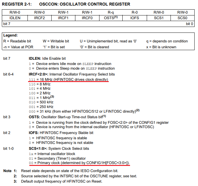
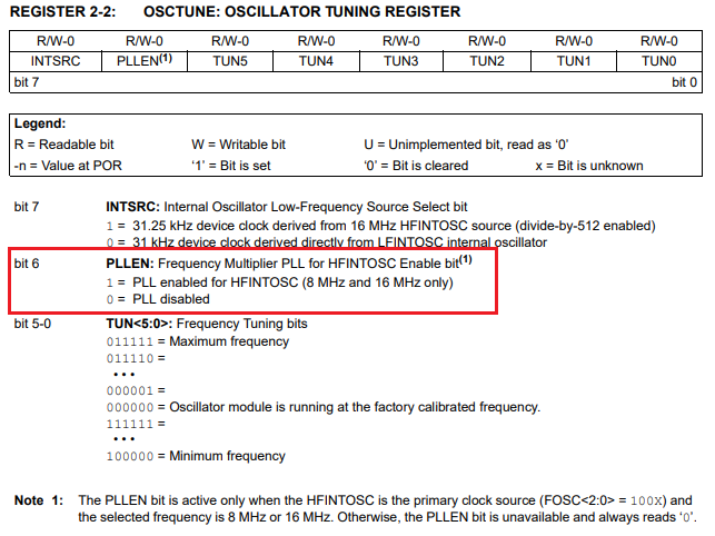
저의 보드에는 크리스탈이 달려있지 않으므로 내부 Oscillator 블럭을 사용하고 PLL을 사용하도록 설정하겠습니다.
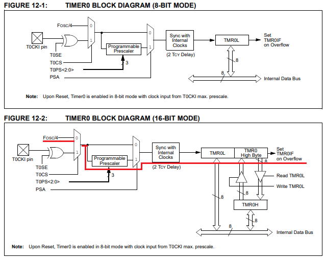
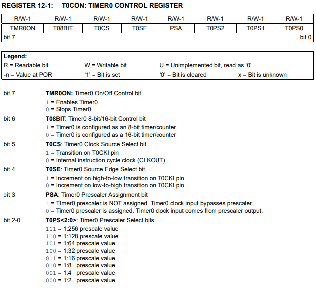
2. 타이머0 설정
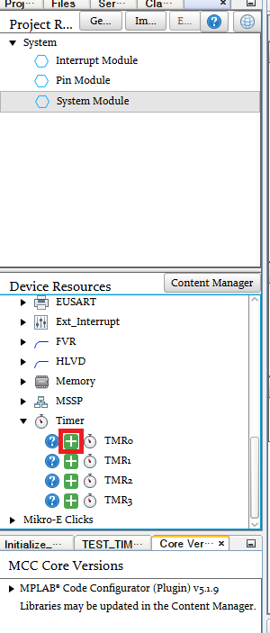
Device Resources에 TMR0를 +클릭합니다
TMR0 Resource 추가
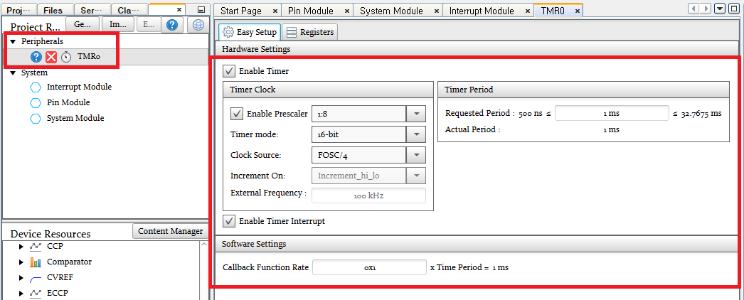
그러면 Peripherals에 TMR0가 나타나게 되고
저는 1ms마다 인터럽트가 발생되도록 아래와 같이 설정했습니다.
TIMER 0 설정
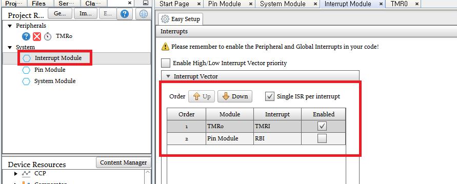
3. 인터럽트 설정
System > Interrupt Module 페이지로 가면 TMR0 인터럽트가 Enabled 된 것을 확인합니다.
TMR0 인터럽트 Enabled 설정
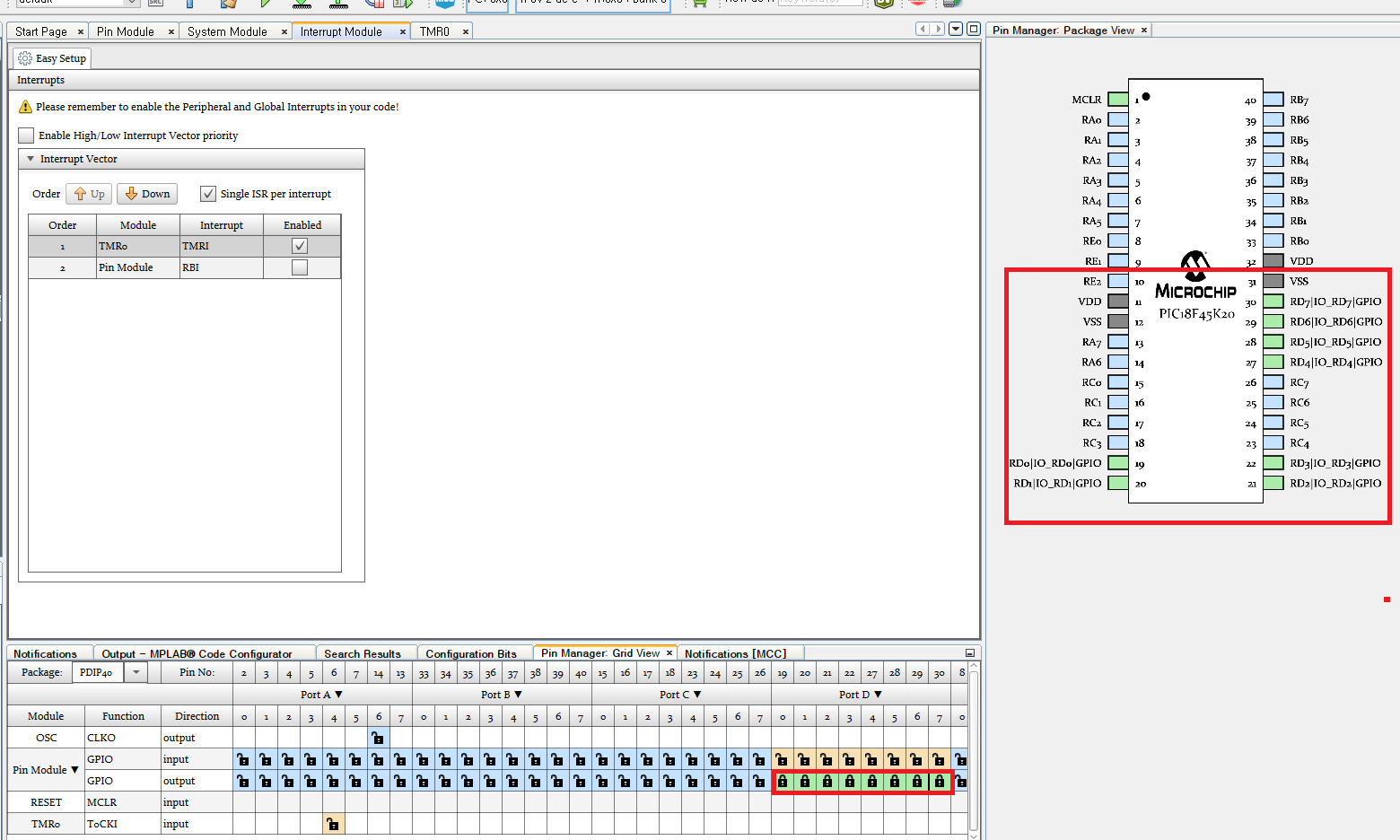
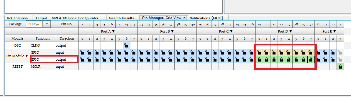
4. GPIO 설정
타이머가 정상 동작하는지 눈으로 확인하기 위해 GPIO를 설정해줍니다.
저는 PORTD0~7번 핀을 Output으로 설정하겠습니다.
GPIO 설정
설정이 완료되었으면 Generate 버튼을 눌러 코드를 생성합니다.
코드 Generate
MCC 프로젝트를 종료하려면 MCC 버튼을 다시 누르면 됩니다.
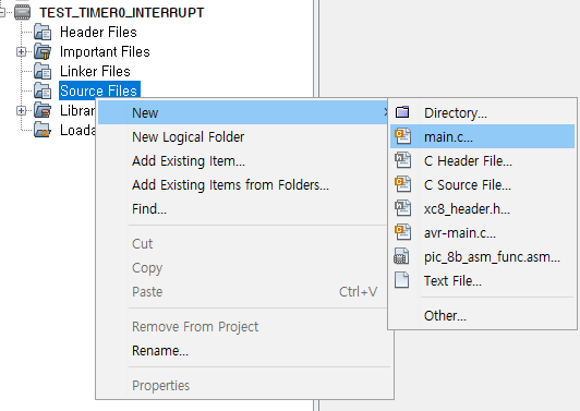
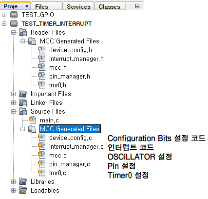
이제 프로젝트 트리를 보면 다음과 같이 코드 파일이 생성된 것을 볼 수 있습니다.
Main.c에 다음과 같이 작성해주었습니다.
#include "mcc_generated_files/mcc.h"
/*
Main application
* 1ms마다 인터럽트를 발생시켜 tick을 증가시키고,
* 1초마다 PORTD 출력을 토글시키기
*/
volatile uint32_t tick = 0;
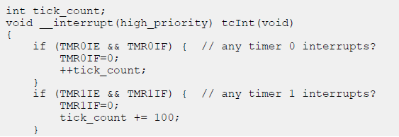
void TIMER0_InterruptHandler(void){
tick ++;
}
void main(void)
{
uint32_t time = 0;
// Initialize the device
SYSTEM_Initialize();
// Timer0 인터럽트 핸들러 설정
TMR0_SetInterruptHandler(TIMER0_InterruptHandler);
// If using interrupts in PIC18 High/Low Priority Mode you need to enable the Global High and Low Interrupts
// If using interrupts in PIC Mid-Range Compatibility Mode you need to enable the Global and Peripheral Interrupts
// Use the following macros to:
// Enable the Global Interrupts
INTERRUPT_GlobalInterruptEnable();
// Disable the Global Interrupts
//INTERRUPT_GlobalInterruptDisable();
// Enable the Peripheral Interrupts
//INTERRUPT_PeripheralInterruptEnable();
// Disable the Peripheral Interrupts
//INTERRUPT_PeripheralInterruptDisable();
while (1)
{
// 1초마다 PORTD 토글
if (tick - time >= 1000) {
time = tick;
PORTD ^= 0xFF;
}
// Add your application code
}
}
/**
End of File
*/
Microchip Embedded 카테고리에 Standalone Project 프로젝트를 선택하고 Next >
Device 를 PIC18F45K20으로 선택하고 Tool은 알맞은 것으로 선택하고 Next >
설치된 XC8 컴파일러를 선택하고 Next >
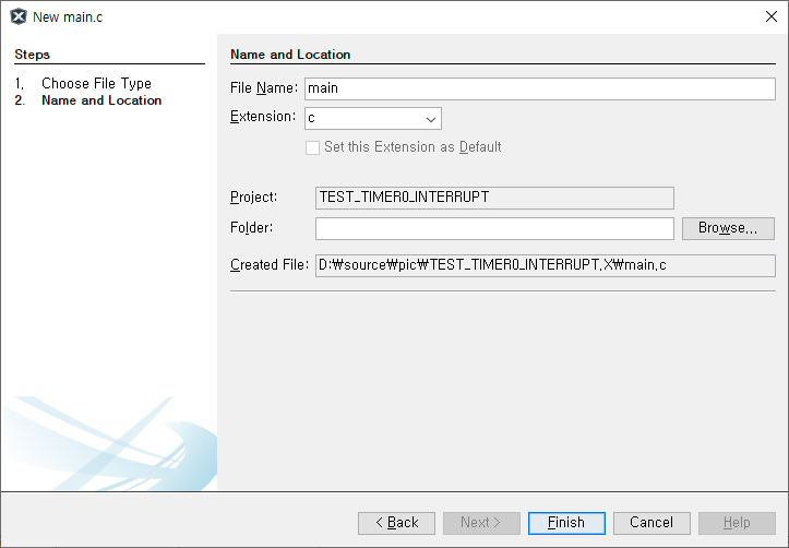
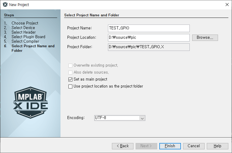
프로젝트 명과 위치를 선택하고, Encoding을 UTF-8로 설정하고 Finish.
그럼 위와 같이 main.c 파일도 없는 프로젝트가 생성됩니다.
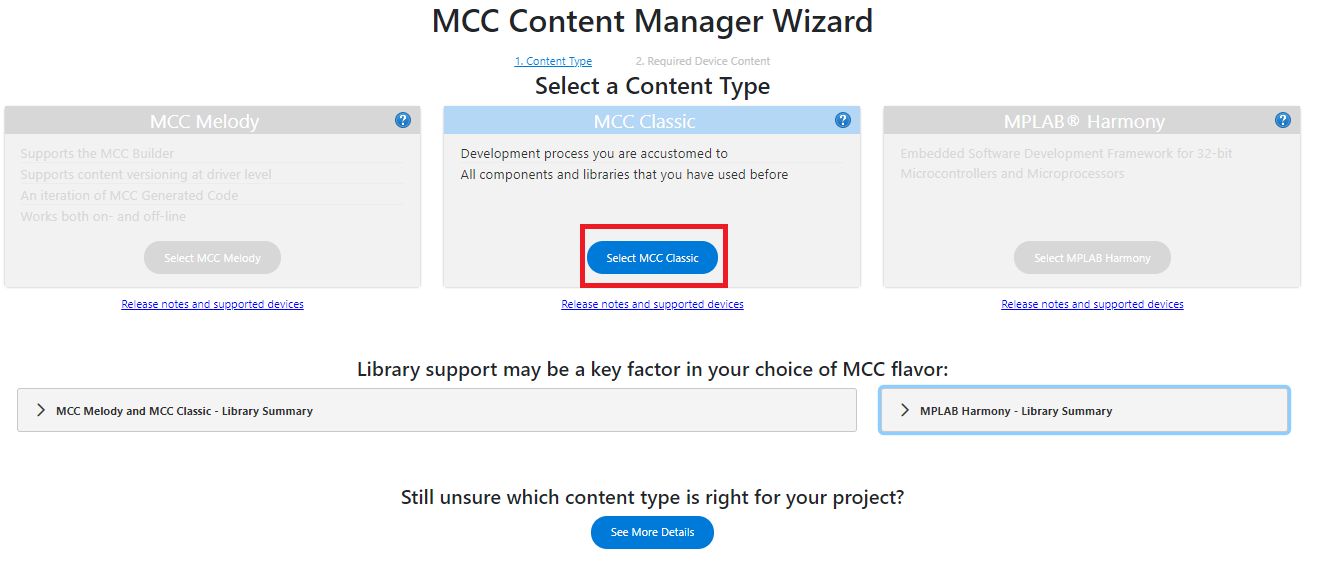
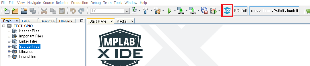
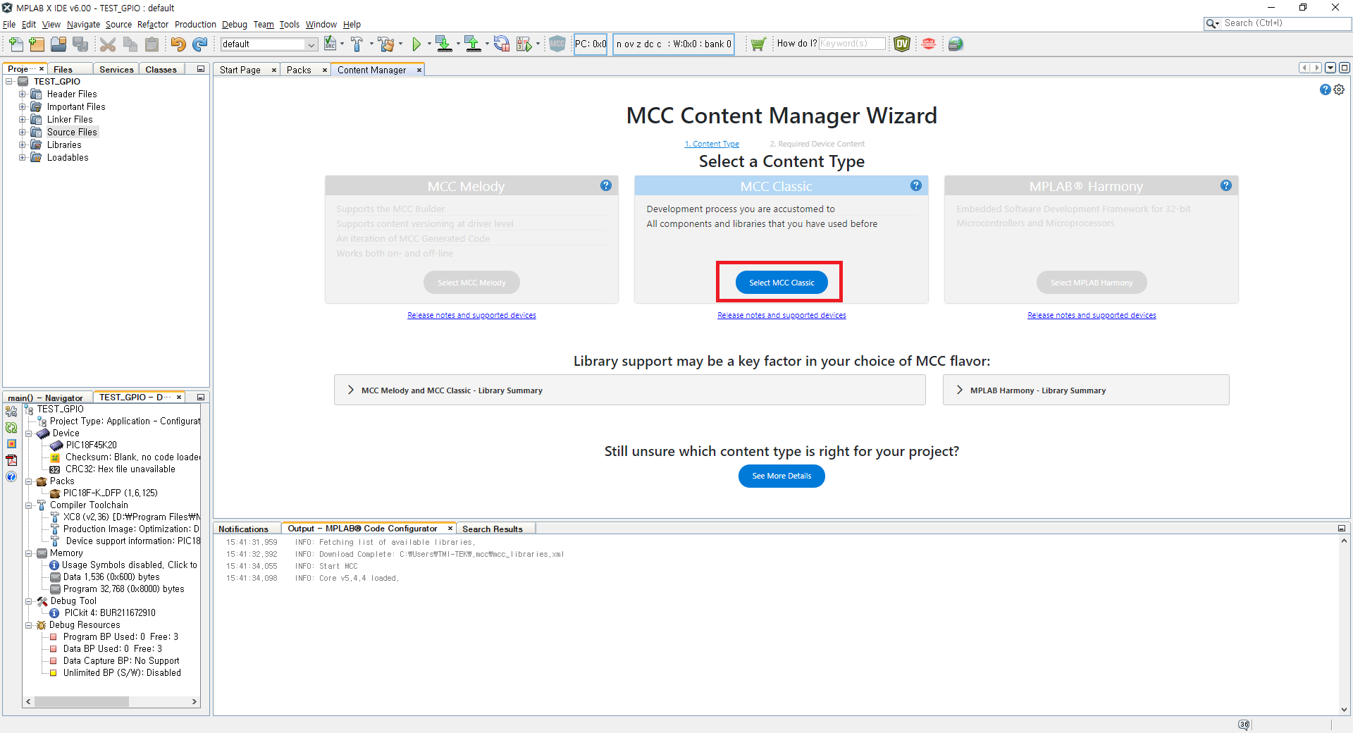
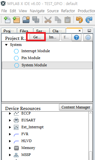
MCC 아이콘을 눌러 아래 페이지가 나타나면 Select MCC Classic을 클릭합니다.
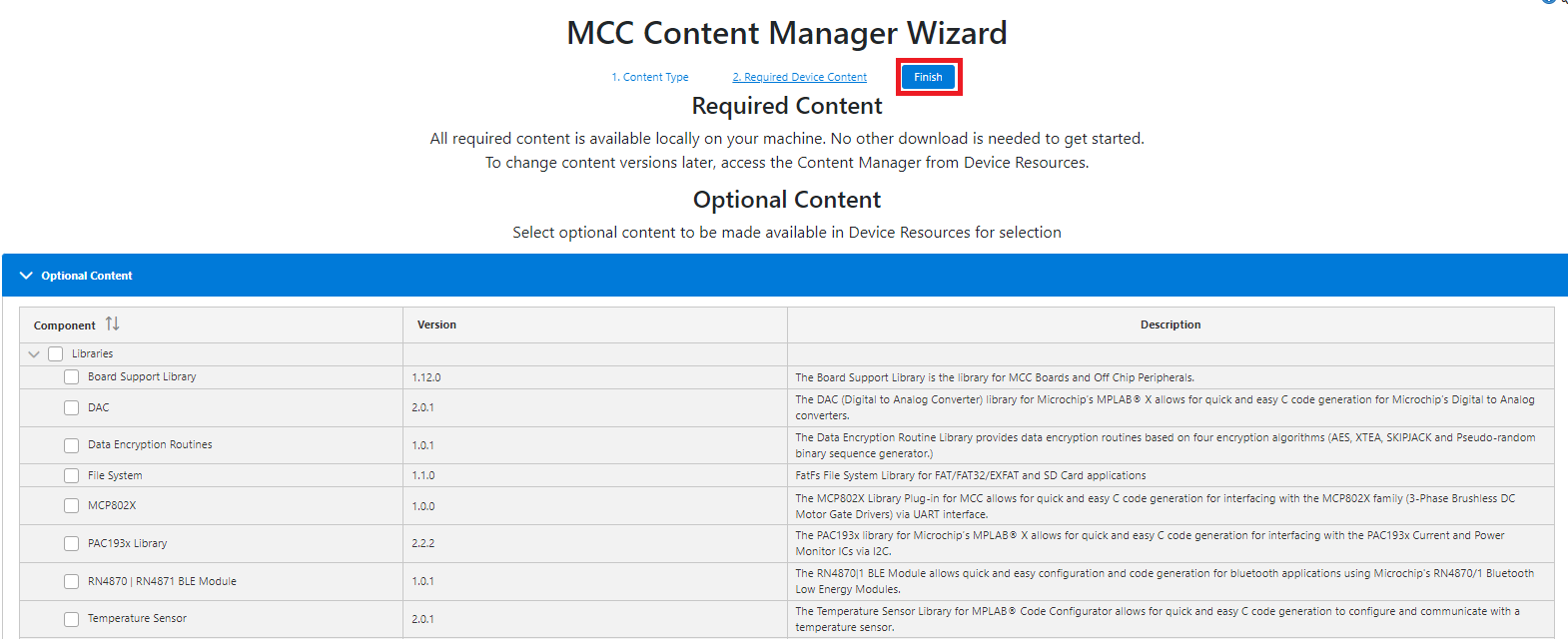
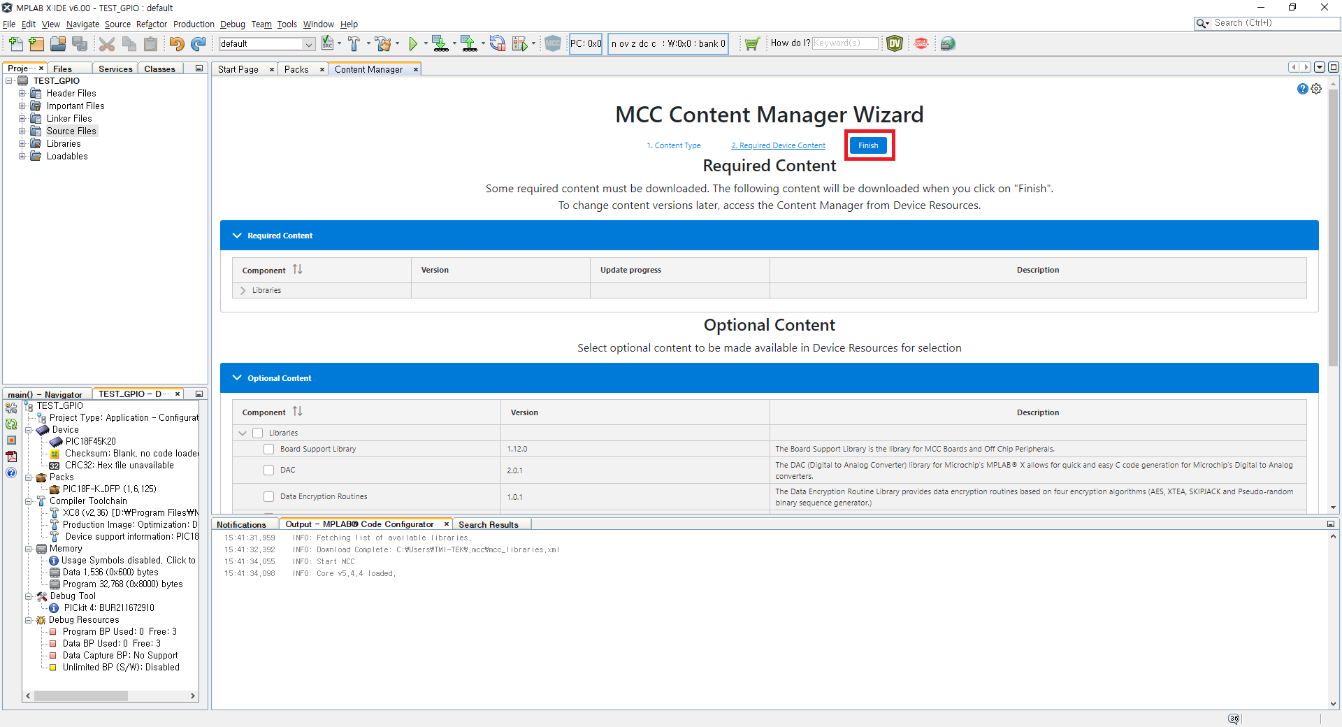
Finish를 눌러줍니다.
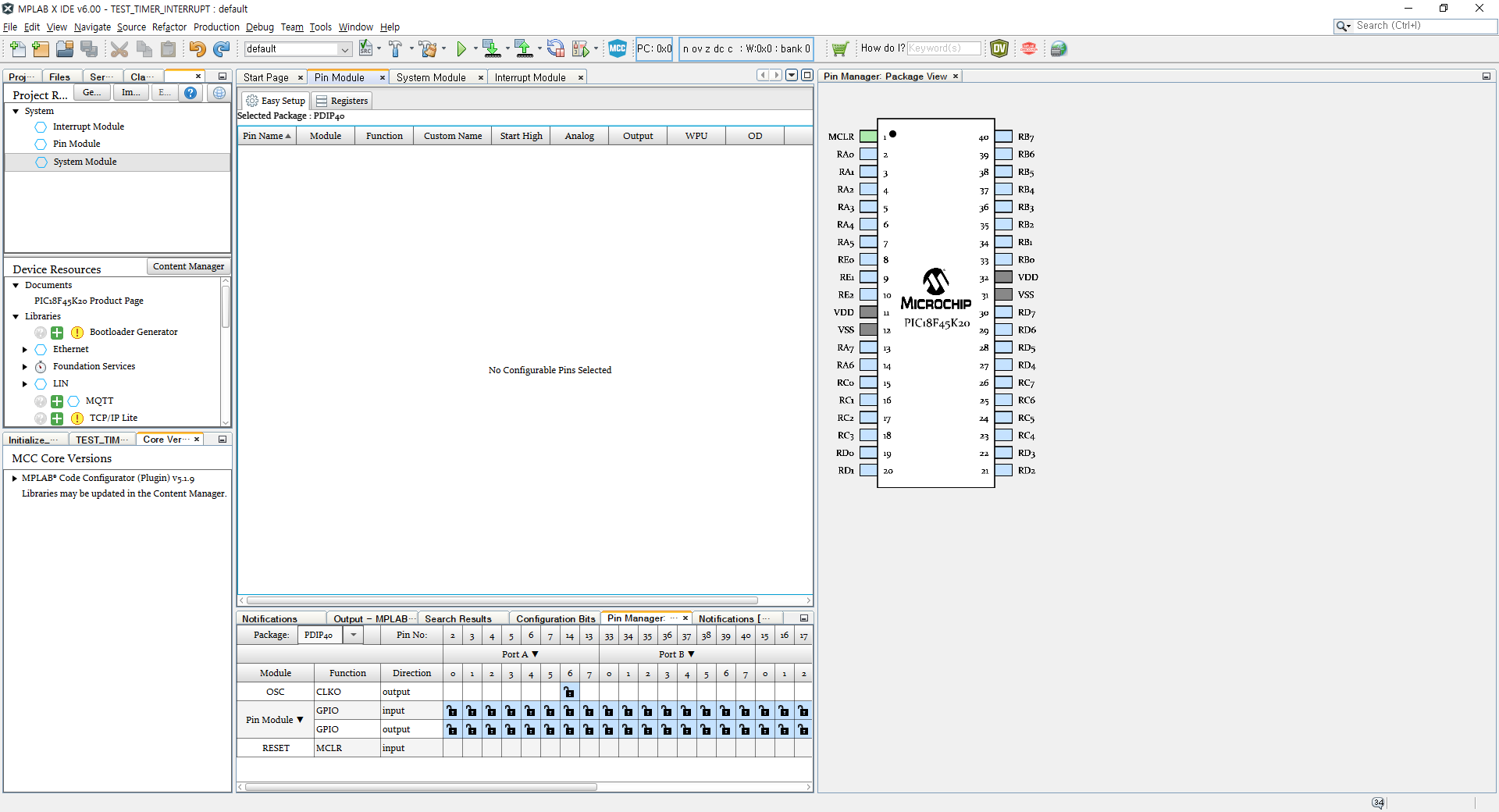
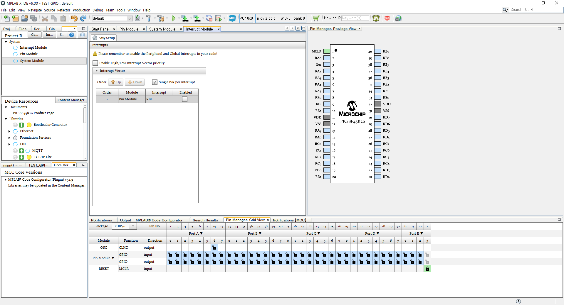
조금 기다리다 보면 아래와 같은 화면이 나타납니다.
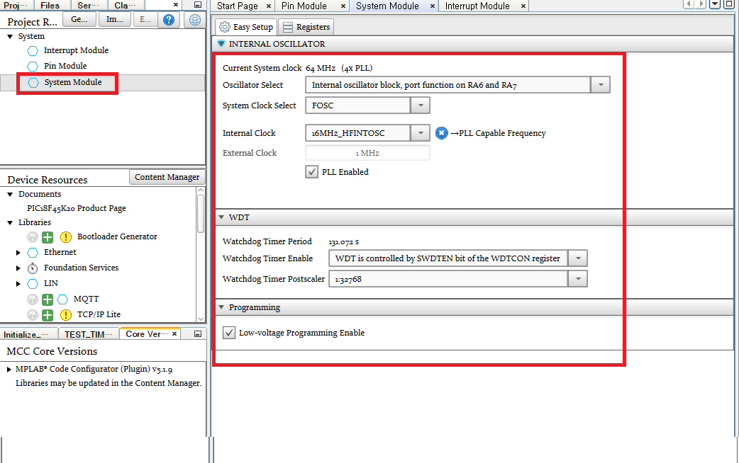
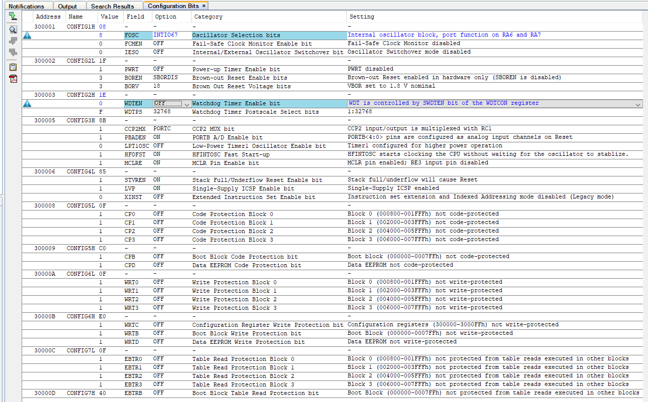
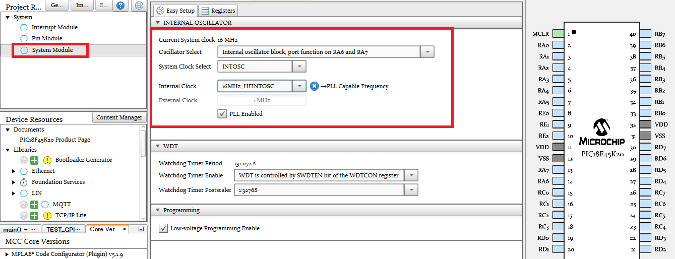
시스템 클럭 설정을 위해 왼쪽 메뉴에서 System Module을 눌러줍니다.
제가 가지고 있는 보드는 크리스탈이 달려있지 않아 내부 오실레이터(INTOSC)를 사용하도록 설정하고,
PLL을 사용하여 16MHz Current System clock으로 설정하도록 하겠습니다.
Pin Module에 PORT D에 output에 해당하는 자물쇠를 클릭하여 설정합니다.
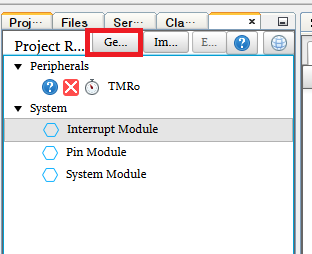
이제 Generate 버튼을 눌러 프로젝트를 생성합니다.
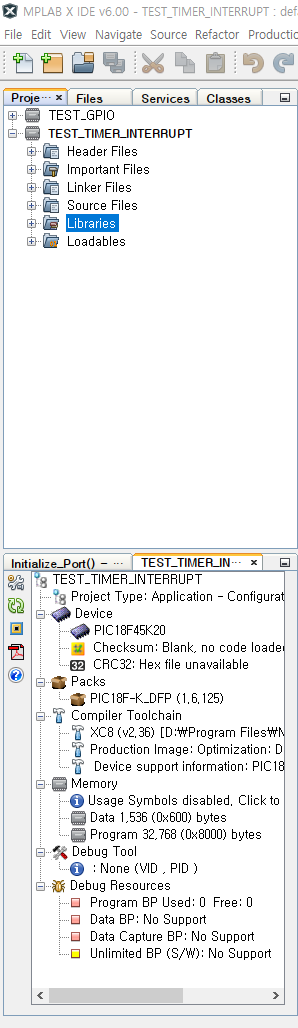
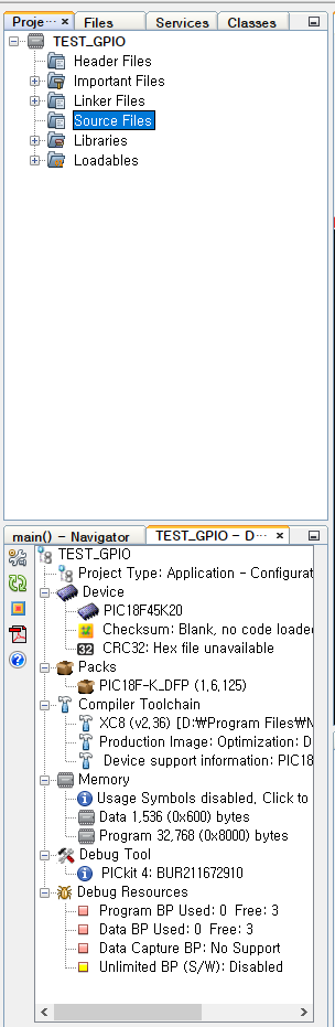
Project 탭을 누르면 아래 화면과 같이 파일이 생성된 것을 볼 수 있습니다.
이제 main.c를 열어 1초마다 PORTD가 토글되도록 프로그래밍 해줍니다.
#include "mcc_generated_files/mcc.h"

/*
                         Main application
 */
void main(void)
{
    // Initialize the device
    SYSTEM_Initialize();

    // If using interrupts in PIC18 High/Low Priority Mode you need to enable the Global High and Low Interrupts
    // If using interrupts in PIC Mid-Range Compatibility Mode you need to enable the Global and Peripheral Interrupts
    // Use the following macros to:

    // Enable the Global Interrupts
    //INTERRUPT_GlobalInterruptEnable();

    // Disable the Global Interrupts

    // Enable the Peripheral Interrupts
    //INTERRUPT_PeripheralInterruptEnable();

    // Disable the Peripheral Interrupts
    //INTERRUPT_PeripheralInterruptDisable();

    while (1)
    {
        PORTD ^= 0xFF;    // PORTD 토글
        __delay_ms(1000); // 1초 딜레이

        // Add your application code
    }
    //INTERRUPT_GlobalInterruptDisable();
}
/**
 End of File
*/
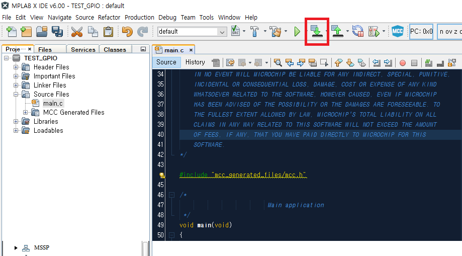
작성이 끝났다면 프로그래머(PICKIT4)를 회로 P1에 연결하고,
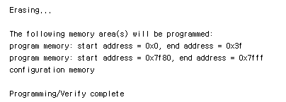
아래 버튼을 눌러 컴파일 & PIC18F45K20에 다운로드 해 줍니다.
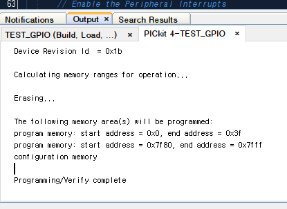
성공적으로 다운로드 되었다면 아래와 같이 Programming/Verify complete 메세지가 나타납니다.